Auger-based
extrusion subsystem
for construction 3D printing
Designing a modular printhead to extrude cement-based materials at construction scale.
Why this matters
3D printing for construction is a young field. The lab where I worked had an existing mid-scale gantry printer with a piston-based extruder — a syringe pushing paste through a nozzle. It worked, but had three persistent operational bottlenecks:
- Cleanup is brutal — cement hardens fast; piston disassembly and cleaning take a long time
- Reload is manual — each print needs full pre-mixing, loading, and pressurizing
- Reconfigurability is poor — changing nozzle, scale, or material often means rebuilding the extruder
My task: design a replacement printhead that reduces these frictions, integrates with the existing control architecture, and remains reconfigurable for future material and scale experiments.
How I solved it
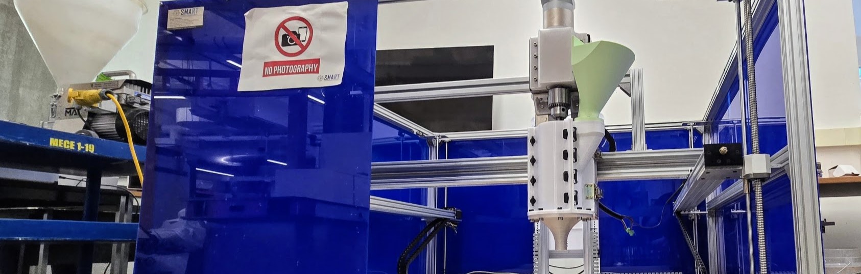
Chose an auger-based mechanism: a rotating screw pushes material continuously through an exchangeable nozzle, replacing the discrete batch-and-push behavior of a piston.
Why auger over piston
- Continuous extrusion — no mid-print reload pauses
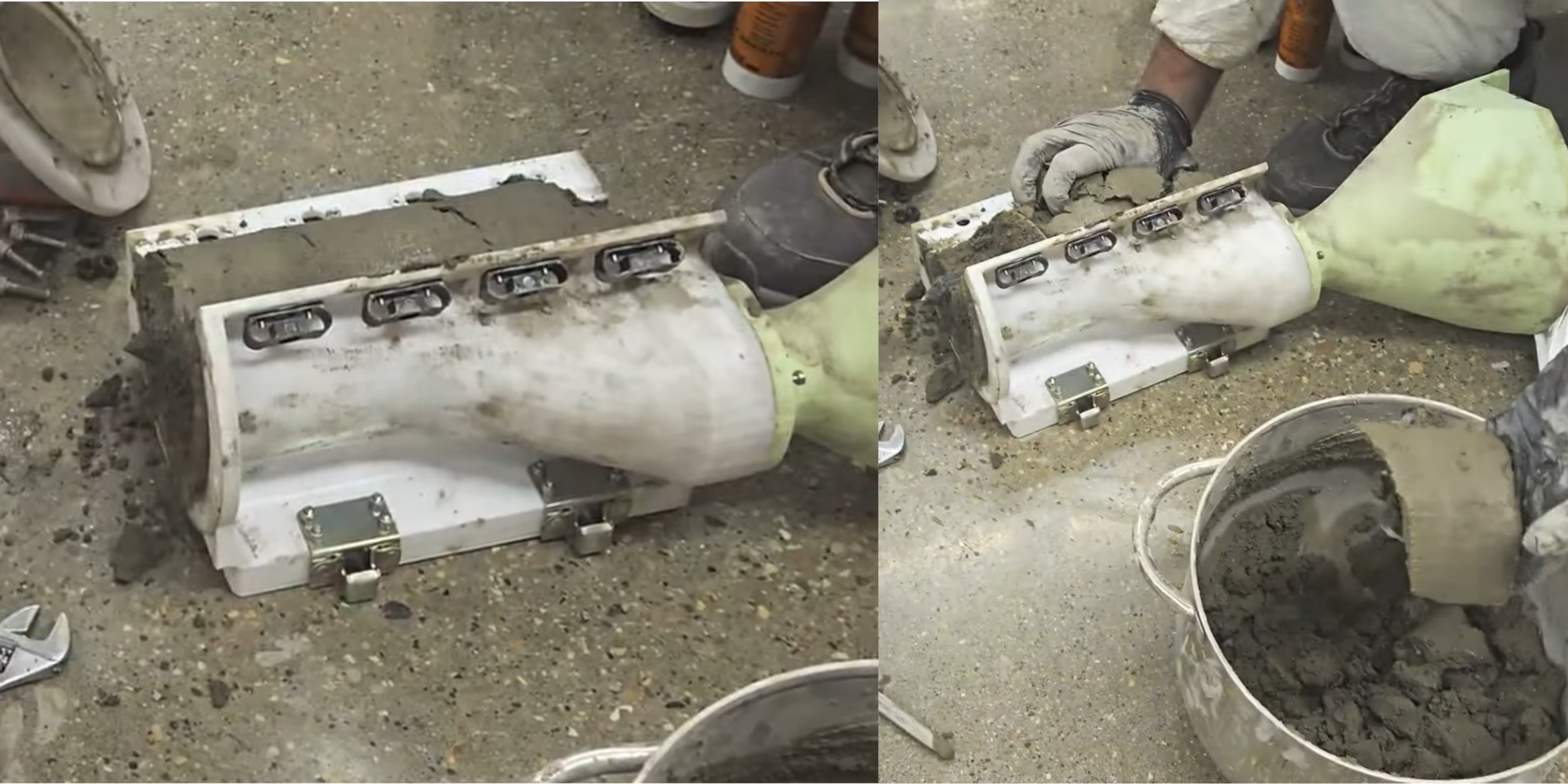
- Faster cleanup — the screw can self-purge by spinning
- Mechanically simpler wetted path — fewer seals, less friction
Multi-domain ownership
The printhead required end-to-end work across four domains, all of which I owned:
| Mechanical design | Sized auger geometry by adapting polymer-extrusion drag-pressure models to cement-based materials. Designed a modular system: separable actuation module and wetted module, with quick-release interfaces. |
|---|---|
| Drive train | Selected a 400 W DC servo (1.27 Nm rated, IP65, integrated brake), 50:1 NEMA 34 gearbox, flexible coupling, and drill chuck with Jacobs taper for tool modularity. |
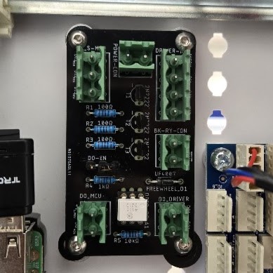
| Electronics | Custom PCB for servo driver digital I/O. Integrated 48V/600W power supply, regenerative braking resistor, and power relay into the existing Duet 3 control box. |
| Firmware | Configured Servo Tuning Software, updated config.g on the Duet 3, implemented PULSE/DIR control through G-code, documented future MODBUS roadmap. |
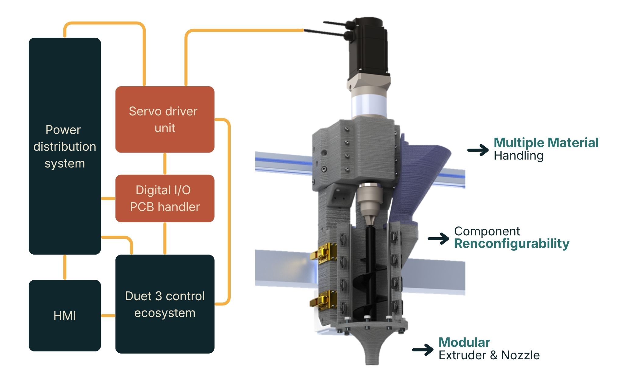
Key trade-offs evaluated
- Auger vs. piston extrusion
- Stepper vs. DC servo vs. BLDC motor
- Outlet diameter vs. aggregate size
- Modularity vs. fastener count
Validation framework
Derived 9 formal design requirements from prior system bottlenecks and literature. Each requirement was validated through inspection, analysis, dry test, or material test.
What it achieved
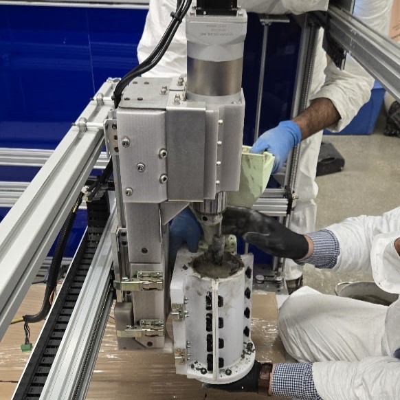
Tested against cement-based premixes with up to 2 mm aggregates (Sand Mix, Mortar Mix variants), printing straight-line, multi-layer test prints (2–3 layers stacked).
Video — Printhead extruding mortar mix
Limitations identified for future iteration
- Hopper feeding behavior needs refinement (occasional bridging)
- Drill chuck loosened under high-resistance conditions — future versions need a more robust tool interface
- Initial nozzle geometry failed during testing; alternate geometries were fabricated overnight to recover the test cycle
Published
IMECE 2026 · ASME, Vancouver — accepted
Related work
- State-of-the-art review · Construction Robotics (2025)
- Performance assessment of the predecessor piston printer · Construction Robotics (under review)
Process & details